Demanding specifications for ambient illuminations are a challenge for tool building. Increasing lengths of lightguides, and space restrictions are mainly responsible for high tooling costs. Without a proper CAD design respecting feasibility studies, illumination simulations and moldflow analysis, the cost calculation of complex lightguide tooling is not possible. Mechanical changes during development process have impacts on the illumination performance and feasability. To avoid extra tool change costs, computer simulations are an essential tool.
By using CAD and light simulation tools we are able to forecast potential impacts on feasibility and estimate tooling cost in an early stage of the development process .
We use the software LUCIDSHAPE as simulation tool in order to simulate the optical performance. The CAD data used is based on CATIA V5.
Moldflow Analysis is used as well as thermal simulation on the PCB layouts.
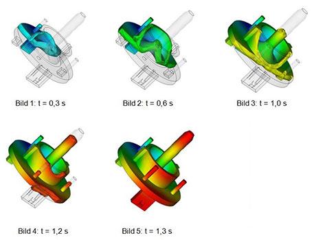
Simulation of the injection moulding process
Design restrictions are demanding challenges and require the feasibility check of various ideas to solve the task. Using CAD and light simulation tools at the same time can reduce the development time and costs significantly. Photo realistic presentations visualize the results in an early stage, and help in desicion making.
The influence of manufacturing tolerances can be evaluated by the use of the simulation tools, manufacturing process tolerances can be calulated and taken into account at an early stage.
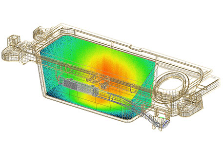
Example of simulation data of an ashtray illuminations
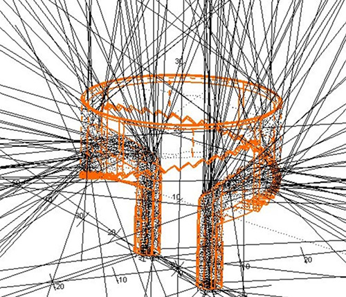
In most cases we use LUCIDSHAPE as lighting simulation software. The data set is based on the origin CAD data and is a powerful tool to visualize the final optical result. Various possibilities to calculate and present the light output help for decision making. Based on the radiation output of the LED we calculate the optical performance of the lightguides by using the LED ray files. Material parameter, surface structures and geometrical aspects are taken into account directly.
We also respect known process- and material properties and deviations during the design of the lightguides. The light simulation therefore is already using the final feasable and toolable design geometry.
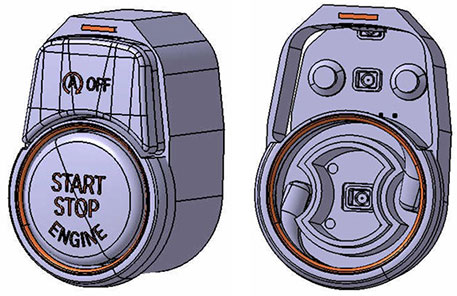
CAD-design example
Our CAD designer are using the software CATIA V5.
This is mandatory for our projects in the car industry. We are working with software releases R16 +. Alternatively we may use SolidWorks for your customized design.
Safe data exchange via our own FTP-Server, or via the KVS portal for data exchange with the VW-group. We always respect and follow the customers regulation for data safety and confidentiality.
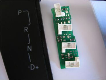
Multilayer pcb for PRND-illumination
We also design customer specific electronic circuits and customized LED driver boards at our electronic manufacturing site in Paernu, Estonia, by using state of the art simulation and design software. We create the gerber files and optimize the thermal layout of the PCBs ourselves in order to find the smallest package solution.
The circuits range from a simple voltage supply to LIN-Bus coupling and PWM drive circuits for calibrated RGB diodes. Customer specifications for drive electronics are followed as well as automotive EMV/EMC regulations. Our equipment is able to handle simple FR4 boards, flexible PCBs, and multilayer PCBs. We run two very flexible SMD lines and use electronic components from tape&reel, sticks, trays and all other packages for automated pick&place.
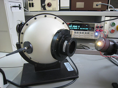
Ulbrichts sphere, precision device for light measurent
The customized design of illuminated applications requires the equipment for light and colour measuring.
Performance studies on prototypes and quality checks of optical components are performed at our own optical lab in Nuremberg, Germany. We run all necessary equipment to demonstrate the performance and optical characteristics of our designs and compare the data with our simulation results. This comparison is also used for the continuous improvement of our optical designs. With our calibrated equipment we can measure colour, lumious density and luminous flux of smallsized and also large scaled devices.
We use this equipment mainly for our own projects, but also offer light and colour measurements as a service. This also includes the inspection of incoming goods or LED sample testing.
| CAD: | CATIA V5 |
| light simulation: | LUCIDSHAPE, SPEOS |
| thermal simulation: | Salome, Paraview |
| LED Measure: | Optronic OL770 Spectroradiometer |
| luminous density/colour: | TechnoTeam LMK 98-4 color |
| Thermography: | Testo 875 IR Camera |
| environmental simulation: | Vibration/random noise (combined with thermal load) mechan. Shock thermal Shock Humidity, Heat, Lifetime |